This section includes installation guides and wiring diagrams for Falken FlightView v3 and v2. Be sure to select the appropriate version as the hardware differs significantly between these two versions. Please also note the “Frequently Asked Questions” link below – this covers dozens of common issues.
FlightView v3 Hardware
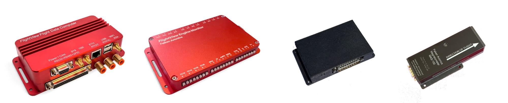
FlightView v3 Installation Guide – Covers the installation of v3 FDC and EMS hardware.
FlightView v3 Wiring Diagrams – Includes pinouts for DB9 and DB37 connectors.
FlightView v3 Mounting Diagrams – Footprint and dimensions for FDC, EMS, FlightDock and FlightDock mini
FlightView WAAS GPS Diagram – Footprint and dimensions for the extenal-mount Falken WAAS GPS
Falken Magnetometer Installation Guide – covers the process of installing and connecting the Falken Magnetometer.
Falken Magnetometer Drawing – 1:1 dimensional drawing of magnetometer for installation.
FlightView v2 Hardware (“FlightBox Pro”)
FlightView Installation and User Manual (Live Version) – The definitive guide to installing and using FlightView. Continuously updated, so check back frequently. A downloadable PDF copy is available here.
FlightView Firmware Updates
Instructions for updating the system firmware on the FlightView Flight Data Computer (FDC) – Covers automatic updates via the FlightView app and manual updates via USB flash drive.
General
FlightView Frequently Asked Questions – our comprehensive FAQ document for answers to many common FlightView questions.
FlightView Training Video Playlist – Our growing library of FlightView training videos.
This section covers the FlightView iOS application which includes a primary flight display (PFD), moving map multi-function display (MFD), engine monitor display (EMS), various situational awareness (SA) tools, and interfaces for controlling COM radios, transponders, and autopilots.
The v3 version of the application can be used with both the v3 and v2 FlightView hardware. Some functions are only available when connected to a v3 hardware system.
Documents
FlightView v3 Pilot’s Guide – Configuration and operations manual for FlightView v3 systems.
Video Tutorial
Watch our comprehensive FlightView application video tutorial. Start off with a review of the core features. Briefly discuss the architecture. Walk through the process of installing the app from the App Store, and then dive into a screen-by-screen review of the key elements of the app.
Install The App
The FlightView app is currently available from Apple’s App Store. To install the FlightView app, search for “FlightView EFIS” in the App Store or click this link in Safari on your iPad.
Get Credentials
To complete the installation of FlightView, you’ll need a user name (typically your email address) and a password. Click here to request your credentials. (Note: this is limited to customers who have purchased FlightView hardware.)
Password Reset
Click this link to reset your FlightView password.
General
FlightView Frequently Asked Questions – our comprehensive FAQ document for answers to many common FlightView questions.
FlightView Training Video Playlist – Our growing library of FlightView training videos.
This section covers the Falken EMS stand-alone engine monitor system which has NORSEE approval for installation in a certified aircraft. The full stand-alone EMS system consists of the Falken EMS hardware, various probes and senders that connect to the EMS, and an iOS application that displays the data.
Documents
Falken EMS NORSEE Installation Guide
Engine Probe Recommendations
See the list of recommended probes to find the right probes for your engine.
Install The Falken EMS App
The Falken EMS app is available for free on the Apple App Store. Use the link or search for “Falken EMS” to install it.
FlightDock v2
FlightDock and FlightBar Installation Guide
FlightDock Mounting Diagram – full scale (1:1) PDF template for mounting
FlightDock Dimensional Drawing – half scale (1:2) PDF document
FlightDock v2 CAD (DXF) file – half scale (1:2)
FlightDock Mini
FlightDock mini Mounting Diagram – full scale (1:1) PDF diagram
Falken Thermoelectric Cooler (TEC)
FlightDock v1 (Legacy Product)
FlightDock v1/FlightBar Installation Guide
FlightDock v1 Mounting Diagram
TT2x Wiring Diagram
Trig TT2x Integration Guide
Connecting a Trig TT2x Transponder with FlightView
Pre-Made Harness
The TT2x transponder connects to FlightView using an RS-485 port on the FDC v3 37 pin DSub connector. If you purchased the factory built TT2x harness the interface is done via the 9 pin connector on the harness normally used to connect the control head. Connect the TMAP A and B pins n the 9 pin connector with the RS-485 Port 1 A & B pins on the FDC.
DIY Harness
If you opt to build your own harness you can connect the TMAP A and B pins on the transponder body directly to the RS-485 Port 1 pins on the FDC. You may use either set of TMAP A / B on the transponder’s 25 pin connector: they are internally joined.
Powering On The Transponder
Note that you will also need to connect the transponder’s Power ON pin to a ground pin (or directly to ship’s ground) to get the transponder to power up. This can simply be a permanent link from the Power On to one of several available ground pins on the transponder. If you prefer you can connect Power On through a switch on the panel.
Use Caution
The Power ON pin is not the same as the “Controller Power” pin. If you connect Controller Power to ground you create a dead short and will damage the transponder.
The transponder is not reverse-voltage protected: reversing ground and power will damage the transponder.
Connect all other pins on the DB-25 as per the Trig documents. See the integration guide and wiring diagram above for details.
Documents / Diagrams
TY91 Wiring Diagram – Direct Connection
TY91 Wiring Diagram – via TC90 Control Head
TY91 Installation and Integration Guide
Installing a Trig TY91 COM Radio
There are two options for connecting FlightView with the TY91. If you did not purchase the optional Trig TC90 control head and will be controlling the radio directly from FlightView you will need option 1: RS-485 Direct To TY91. If you purchased and installed the optional Trig control head, you will use option 2: RS-232 To TC90 Control Head.
See the above TY91 Installation and Integration Guide and the wiring diagrams for details.
FlightView RS-485 Direct To The TY91
Using a direct connection between FlightView and the TY91 radio saves panel space and a small amount of money by foregoing the control head. In this case, all configuration of the radio is handled through FlightView. The active frequency is set using the standard FlightView COM screen. Radio options including volume, squelch, side-tone, and intercom config are handled through the COM 1 or COM 2 screen in system settings.
The TY91 uses Trig’s TMAP protocol to communicate with FlightView. The physical link used to establish the connection is an RS-485 port on the FDC v3 37 pin DSub connector. This ties to the “TMAP” inputs on the transponder or, if you purchased the optional factory harness, on the DB9 connector that would normally connect to the control head.
A wiring diagram showing a direct connection from FlightView to the TY91 is available here.
FlightLink RS-232 to the TC90 Control Head
Connecting FlightView to the TC90 control head allows you to use either the Trig TC90 control head or the COM interface in FlightView to set the active frequency. All other configuration (volume, squelch, side-tone, etc.) is handled by the control head. This option is good if you have the panel space for the control head, as it gives you two methods for controlling the TY91 radio.
The TC90 control head has an RS-232 communications port that “speaks” the Garmin SL-40 protocol. To interface this with FlightView, you will need an available RS-232 port on the FDC v3 to interface.
A wiring diagram for connections using the TC90 control head is available here.
Falken BusBox is a power distribution system for Experimental and Light Sport aircraft. It uses common ATO/ATC automotive fuses and can support up to 30 circuits, with 15 configured as always-on main bus circuits and another 15 avionics bus circuits that are controlled by the avionics master switch.