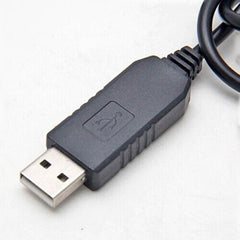
One of the top three requests I’ve received since launching FlightBox is a way to send the ADS-B data to an EFIS or MFD. FlightBox usually delivers ADS-B and (optionally) GPS data to a display system over Wifi. This works very well for tablets and newer portable navigators, but there are many in-panel displays that do not have a Wifi interface. Most of these use the RS-232 serial standard instead. To get the data from FlightBox to an RS-232 port on an EFIS we use a USB-to-serial converter. This posed a bit more of a challenge than you might imagine, as most GPS devices also use a USB-to-serial converter.
If a GPS and the RS-232 output adapter both use the same USB-to-serial chip, they show up in the Raspberry Pi as something like “usb_serial1” and “usb_serial2”. To make matters more challenging, they don’t always get the same assignment – whichever device initializes first becomes “1” and the next becomes “2”. This leads the system thinking the GPS is disconnected or broken while pumping ADS-B data at it, instead of the display system. Not good.
To solve this, we found a USB-to-serial adapter that allows us to program a custom “name” for each device. (We do something similar to the radio modules to keep the 1090 and 978 functions associated with the correct module.) We currently have a limited number (as in, 8) of these adapters in stock. More are on the way. I’ve not added them to the default catalog on the web store, but you can find them here.
Each kit comes with the 6′ adapter cable (ends in bare wires), a 6″ USB pigtail cable, and a wiring guide. The adapter has six wires, but only two – transmit and ground – are required for most ADS-B In applications. The output from the adapter uses the RS-232 protocol and should not be connected to “TTL serial” inputs which use a different voltage range. (Most if not all avionics use RS-232, but check before hooking something up.)
The system defaults to a baud rate of 38,400 bps, 8 data bits, one stop bit, and no parity. At this point the data bits, stop bit, and parity are fixed, but we have included a field in the Settings tab of the web application to adjust the baud rate. Some hardware, including the iFly GPS systems, requires the baud rate be adjusted up to 115,200 bps.
Thus far, the serial output has been successfully tested with systems from GRT (big thanks to Greg Toman), iFly GPS (big thanks to Shane Woodson), and a Chelton MFD. FlightBox uses the industry standard GDL-90 format, which means that it should work with many other EFIS and MFDs.
Installation – FlightBox Side
There is one potential issue with installing the serial output. It uses the top-center USB port on the Raspberry Pi – the same port we have been using for the GPS. In many cases that won’t be a problem – if you’re using the FlightBox in an aircraft with an EFIS or MFD, you probably don’t need a GPS. In some cases, however, users will want both. If you need to have both the serial output and the GPS connected, you have two options – you can use an external USB hub or you can make some modifications to your FlightBox case. (If you have an early FlightBox unit with a Raspberry Pi 2 and a USB Wifi module you will need to use the USB hub option.)
The USB hub option is the least invasive but costs a bit ($10 – $15) and adds another potential point of failure. You can use a simple non-powered hub as neither the GPS nor the RS-232 adapter draws any appreciable current. Amazon offers a number of basic two-port USB hubs that should work. I’ve ordered this one and will be trying it out.
The case modification procedure requires you remove one of the three cleats that hold the top on (the other two do a more than adequate job) and make a small incision in the end of the case (opposite the top-right USB port) to allow another USB cable to exit the box. Needless to say, you do this at your own risk.
Installation – Display Side
The RS-232 cable ends in six bare wires. The only two that matter for ADS-B are the black ground wire and the orange transmit line, both of which will need to be connected to pins on your display system. Unfortunately, there is no universal standard for serial avionics connections, so you will need to consult your avionics system’s manual to determine the type of connector you need. Many use the classic “DB-9” input, while others use DB-15, DB-25, and other, more arcane connectors. The display-side connection will require either crimping or soldering, depending on the connector style.
The iFly 700 uses – wait for it – USB, so you will need a USB to RS-232 adapter. Yes, that’s right, you’ll have two RS-232 adapters back-to-back. (No, you cannot just use a male-USB-to-male-USB cable. Won’t work.)
Installation – Beta Update / Image
If you are interested in trying out the serial output feature, you’ll need to order a cable and to download and install either the beta image or the beta update. The image is useful if you’re technically inclined and have an extra micro SD card available. Follow the imaging instructions here to image your card.
The update is simpler to install, as you simply use the update feature of the Web UI, but may cause issues including bricking your system. We’ve done SOME testing, installing the update on working 1.0r1 systems. We’ve not yet been through the process of testing it on every released build (0.8r2, 0.8r3, 0.8r3a) or every hardware configuration (Pi 2 with USB Wifi module) so your mileage may vary. If something goes wrong, simply re-image with either the beta image or 1.0r1.
Feedback
The reason we’re releasing this beta is to gather feedback from users. If you install the new version and have questions or problems, please post something on our Community Support Forum.
Serial Input?
One interesting side effect of adding serial output is that it comes with serial input. If your experimental avionics package has an output for something useful – engine data, air data, AHRS data, etc., it would be relatively simple to use the available RX line on the serial adapter to feed that information into the FlightBox and broadcast it over Wifi to tablets, etc. Anyone have any suggestions or ideas for what we might be able to do with the serial input?
NOTICE: FlightBox is not approved for permanent installation in type certificated aircraft. Integrating with an MFD or other certified panel mount display system may invalidate the airworthiness of your aircraft. Use caution. Talk with your avionics shop or technician. Do not break the law!

